Arduino-controlled Greenhouse
- Wireless monitoring and control with iOS app
- Powerful and efficient LED grow-lighting
- Automatic ventilation with Humidity & Temperature setpoints
- Illumination scheduling
- View On GitHub
An Introduction
I am an iOS app developer by day, but over the last few months I did some demo projects with Arduino and worked up to implementing custom Bluetooth LE communication using a "shield" by Redbear Labs. The next step was to put everything together into a real project that I could benefit from daily.
The goal of this project is to put together a working greenhouse and in the process to build up my electrical engineering skills. The rapidly growing market for mobile apps is just a few years old but I believe that as it matures one of the main segments will be apps that can integrate with the physical things around us.
I have chosen to start with a small, indoor greenhouse with integrated lighting. I will use a sealed container and various controls to manipulate the growing environment. The first two controls I will implement are the LED lighting system and ventilation control.
I'll add sections roughly in the order that I complete the work with a mix of discussing the options I learned about in my research and instructions on how to recreate my build.
An Overview
Who would this appeal to? For a thrifty gardener this could be a cheap way to enjoy the benefits of a more expensive commercial rig. For an agriculture student it could run an experiment. For the budding programmer it could be a practical exercise in writing code. For the engineering student it could be a fun way to practice control theory. For the advanced gardener it could maintain the microclimate suiting a fussy plant.
How does it work? In my case the greenhouse is a sealed Rubbermaid container filled with plants. To it I've added sensors to detect the humidity and temperature both inside the container and out. To control the interior climate there is a vent that can be opened and closed. To monitor the sensors and open and close the vent automatically I've added an Arduino, a small computer running a pre-loaded program. Finally, I've created an iOS app that communicates with the Arduino wirelessly. From that app you can monitor the status of the greenhouse as well as change settings in the program controlling the greenhouse environment. Those with programming experience will find it easy to modify the program even further to suite their needs.
What can you do with it? Just like a traditional greenhouse, the goal is to create an isolated climate that provides favorable conditions for plant growth. In the initial design we provide plants constant air movement, supplemental illumination, and passive control over humidity and temperature. The next most likely additions would be active control of humidity (a mister), active control of temperature (a heater), and automatic irrigation/feeding. A greenhouse would be great for growing herbs in the winter or starting seedlings before the last frost. You could setup a custom lighting schedule for plants that need special conditions to bloom. You could keep exotic or tropical plants alive in climates they're otherwise not well suited to.
How can I get involved? I've made the Arduino and iOS source code available on GitHub for others to use or build from. This page provides a lot of technical information and explanation of how I put my greenhouse together. With that I hope to share my 2¢ and help others in the future the way similar project pages have helped me. Many sections of this project are new territory for me so I'm very welcoming of feedback and suggestions.
Lighting options
Because it was the furthest outside my comfort zone, I began with the high-power LED lighting system first. From some initial research I learned that Fluorescent tube, High-Pressure Sodium (HPS) and Metal Halide were the traditional choices for grow lighting, listed in order of increasing intensity (and price). The idea of LED lighting systems is not new, but is gaining in popularity as the efficiency of the LEDs increases and their price decreases. NASA has evaluated whether LED lighting would be a good fit for long mission space farming. The more recent "high-power" LEDs are in a different class from those we're familiar with as indicators in our consumer electronics: They consume hundreds of times more power and emit similarly greater amounts of light; these are the components that make LEDs a viable replacement for incandescent or compact-fluorescent light bulbs.
One of the things drawing me to LED lighting was the notion of Photosynthetically Active Radiation (PAR). This is the idea that the compounds in plants that drive photosynthesis (food production) respond better to specific colors of light. In a nutshell, very little light outside of the visible range (i.e. ultraviolet (UV) and infrared) is beneficial to photosynthesis and even within the visible range most colors between red and blue contribute very little. Looking at the Yield Photon Flux table, I chose to target the 440nm and 620nm peaks, which are the most efficient at stimulating photosynthesis.
LED constant current driver
These days there are tons of commercial LED grow light fixtures available for purchase, ranging from tens to thousands of dollars. The ones that realistically mimic the light output of professional grow lights typically use 10s to 100s of the 1W (1 watt) or 3W LED components. With a per-piece cost of $1-$5, these fixtures often cost hundreds of dollars.
Given the large fixed cost of the components themselves, I decided to try and save on the labor costs and build my own high-power LED lighting system. I based my design heavily off the instructions on Dan Goldwater's LED power supply tutorial. Specifically, I started from the constant-current design in Step 6.
To save on shipping, I mostly used components I could get locally:
- IRF520N HEXFET power transistor (in place of Fairchild FQP50N06L)
- 2N3904 NPN transistor (in place of Fairchild 2N5088BU)
- 100 kOhm resistor
- 2x 0.47 ohm (up to 5W) and 2x 1.0 ohm (up to 10W) power resistors from RadioShack
- Intocircuit 120volt to 12-volt/30-watt power supply
I started out with a basic knowledge of Ohm's Law (i.e. V=IR) and Kirchhoff's voltage law, but had a difficult time understanding the constant current circuit. In my design, the Intocircuit power supply is converting 120V AC to 12V DC; the riskier part of the equation I didn't want to mess with myself. However, that power supply will deliver any amount of amps from 0 - 2.5, at 12V, that the net resistance of the circuit will dictate (see Ohm's Law). Our LED components are trickier, because if you connect them directly to the power supply they will draw more current than they need and quickly burn up; sort of like a person who can't control themselves at a buffet. Thus we need to put a constant-current controller between the 12V power supply and our LEDs. In some situations resistors could be used to limit the current flow, but at the high power level of our LEDs even minute temperature-dependent fluctuations in the amount of current they'll pass need to be actively controlled to avoid damage.
Dan's constant current controller design uses the MOSFET power transistor to regulate the current flow through the LED circuit. The smaller transistor constitutes the negative feedback loop that causes the circuit to hold a fixed current flow. Overall I found Dan's description to be helpful, but there were a couple of values for which no explanation was given. In his calculation of LED current and R3 power, he uses the unlabeled constants 0.5 and 0.25. I believe I have identified where they come from, but it requires some brief discussion of how the circuit works:
The Gate pin of the MOSFET is triggered by voltage level; For the IRF520 as little as 5V will turn it fully ON. In Dan's design, a 100 kOhm resistor from +V is used to raise the voltage at the Gate pin and turn the MOSFET, and thus LED string, on. The way in which our small NPN transistor created negative feedback is to open up and conduct from the Gate pin to ground, lowering the voltage at the Gate pin and turning the MOSFET off. The large-value resistor is important to ensure the current flowing through the small NPN transistor is negligible.
How the small NPN transistor creates feedback is to exploit one of its data-sheet properties: VBE(sat), or the Base-Emitter Saturation Voltage. VBE(sat) not only describes a voltage drop across the Base and Emitter pins, but it is also a threshold below which there is virtually no conduction from Collector to Emitter. With R3 in place, we know that the voltage at the Base of the small NPN is VBE = IMOSFET * R3.
- As IMOSFET increases, VBE increases. When VBE reaches VBE(sat) the small NPN starts to conduct from Collector to Emitter and the voltage at the MOSFET's Gate pin drops.
- As the MOSFET Gate voltage decreases, the resistance between the MOSFET's Source and Drain increases, lowering IMOSFET
- Eventually you reach a value of IMOSFET that balances with VBE so that you remain in a steady-current state.
So the unlabeled value 0.5 in Dan's instructions is the VBE(sat) of his small NPN transistor. I measured VBE(sat) of my 2N3904 to be 0.572V. The other constant that went unlabeled was in calculating the power the R3 resistor needs to handle. Dan uses 0.25. Knowing Power = V * I and substituting I = V / R you get P = V2 / R. So it would appear that the constant in his power calculation is VBE(sat) squared.
LED choice and considerations
After doing some research it seemed that the overwhelming consensus is that you can get cheap high-power LEDs from China but the quality is very hit-or-miss. For my first project I wanted to stick to something reliable so I would have fewer things to debug: That left Cree and Luxeon. I did some searching but the product lists at Digikey and Mouser were a little intimidating. I ended up ordering from the Luxeon Star website because their "Rebel" bases specifically mentioned easy soldering with simple tools and they have detailed data sheets for each product. I settled on the Rebel Tri-Star CoolBase models because of the slight discount per-LED over individual LEDs and ordered 6 "Red", 1 "Royal Blue" and 1 "Cyan" Tri-Star. That got my order to over $100 and earned free shipping. The Red and Royal Blue correspond very closely to my target PAR peaks at 620nm and 450nm while the Cyan just adds diversity. I chose the 3:1 ratio reds to blues loosely on observations of the commercial grow lamps.
- 6x Red (627nm) Rebel LEDs, Mounted on a 20mm Tri-Star CoolBase - 306 lm @ 700mA (SR-03-D2050)
- 1x Royal-Blue (447.5nm) Rebel LEDs, Mounted on a 20mm Tri-Star CoolBase - 2670 mW @ 700mA (SR-03-R0800)
- 1x Cyan (505nm) Rebel LEDs, Mounted on a 20mm Tri-Star CoolBase - 366 lm @ 700mA (SR-03-E0070)
- 2x Intocircuit 120V to 12V 2.5A power supplies
It is important to consider your power supplies and constant current driver design when placing your LED order. The constant current driver design is only efficient when the voltage drop across the LEDs is very close to the voltage of the power supply. Any difference is burned off as heat by the MOSFET and just adds trouble. What you want to do is make combinations of LEDs whose Forward Voltage (Vf), the drop in voltage across them at power, adds up nearly to your power supply voltage. For me the power supply voltage is 12V. You'll want to refer to Kirchoff's law for how the Vf combines in series vs. parallel. I ended up with:
- 3 strings with 2 Red, 1 Royal Blue, and 1 Cyan (Forward Voltage 10.85V)
- 3 strings with 4 Red (Forward Voltage 9.2V)
When matching the forward voltage of your strings of LEDs to your power supply, be sure to take into account both the voltage drop of the MOSFET and of R3!
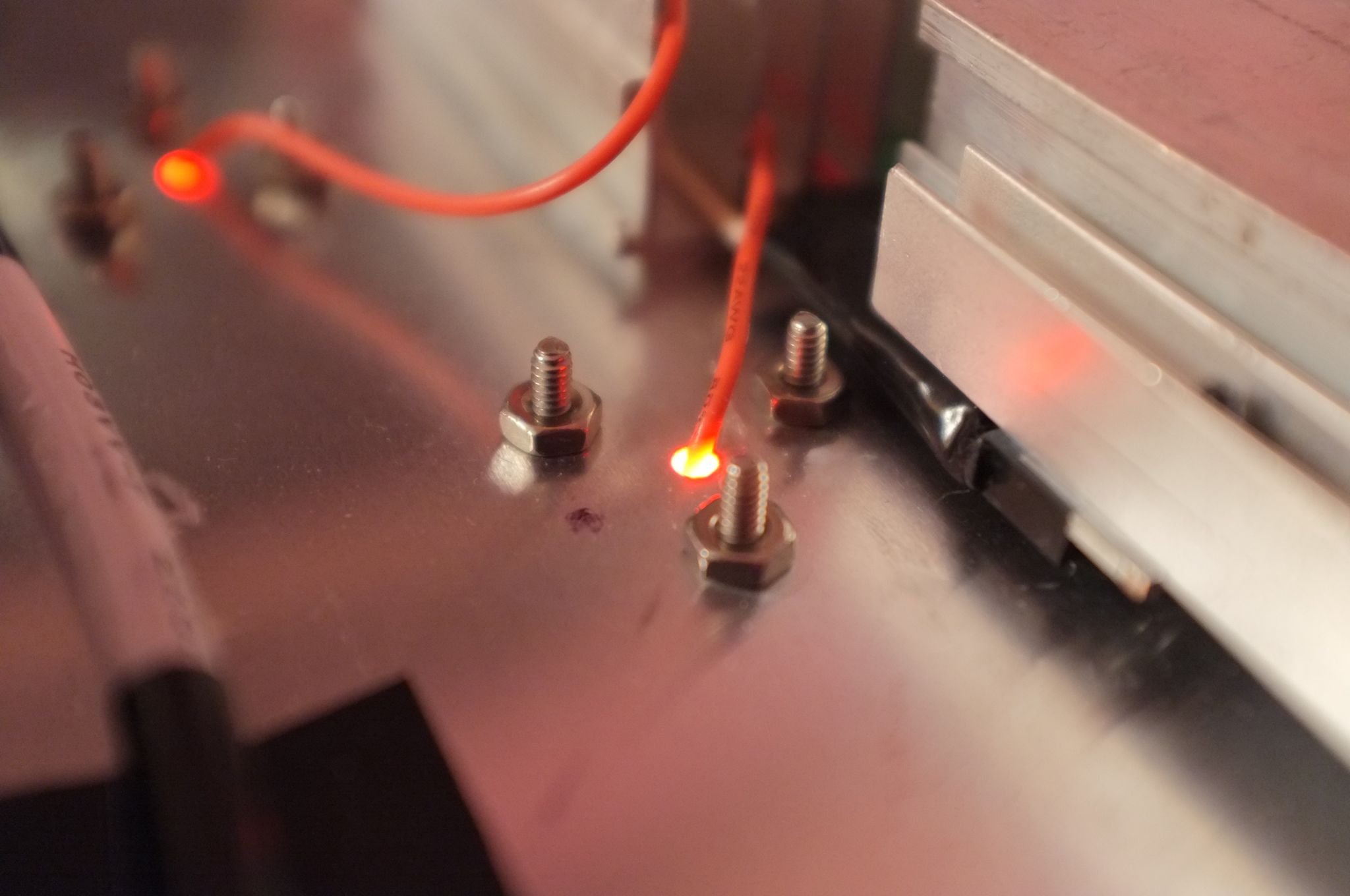
After I wired everything up I discovered a few problems with my plan. First, I neglected to consider voltage drops across the MOSFET and across R3. The voltage drop across the MOSFET is due to what the IRF520N data-sheet lists as RDS(on): The resistance between Drain and Source when the MOSFET is fully ON, i.e. the lowest resistance it will ever have. In my case that is 0.2 Ohm, which at 2.1A is 0.42V. My second and third problems are due to the lack of options I had for low-ohm resistors. I could only find 0.47 Ohm and 1.0 Ohm power resistors that cost about $2.50 a piece. With two 0.47 Ohm resistors in parallel I have R3 = 0.25 Ohm that is pretty close to our goal of 0.572V / 2.1A = 0.27 Ohm. Because the voltage drop across these as R3 was the smallest I paired it with the 10.85V LED string.
Finally, I already had two 1 Ohm resistors so I put those in parallel to get 0.5 Ohm. At 2.1A we would get a voltage across R3 of 1.05V, which is well above the NPN's VBE(sat) of 0.572V. So I built a voltage divider with >1 kOhm resistors and used the output to drive the Base of the small NPN. This allowed me to use the low-ohm resistors I had even though the voltage across R3 was unsuitable for negative feedback. One downside to doing this is that the power dissipation through R3 is higher and generates more heat. The voltage divider isn't just useful when R3 is way off, I also used a voltage divider to fine-tune the current set-point of the other strings too.
Greenhouse construction and venting
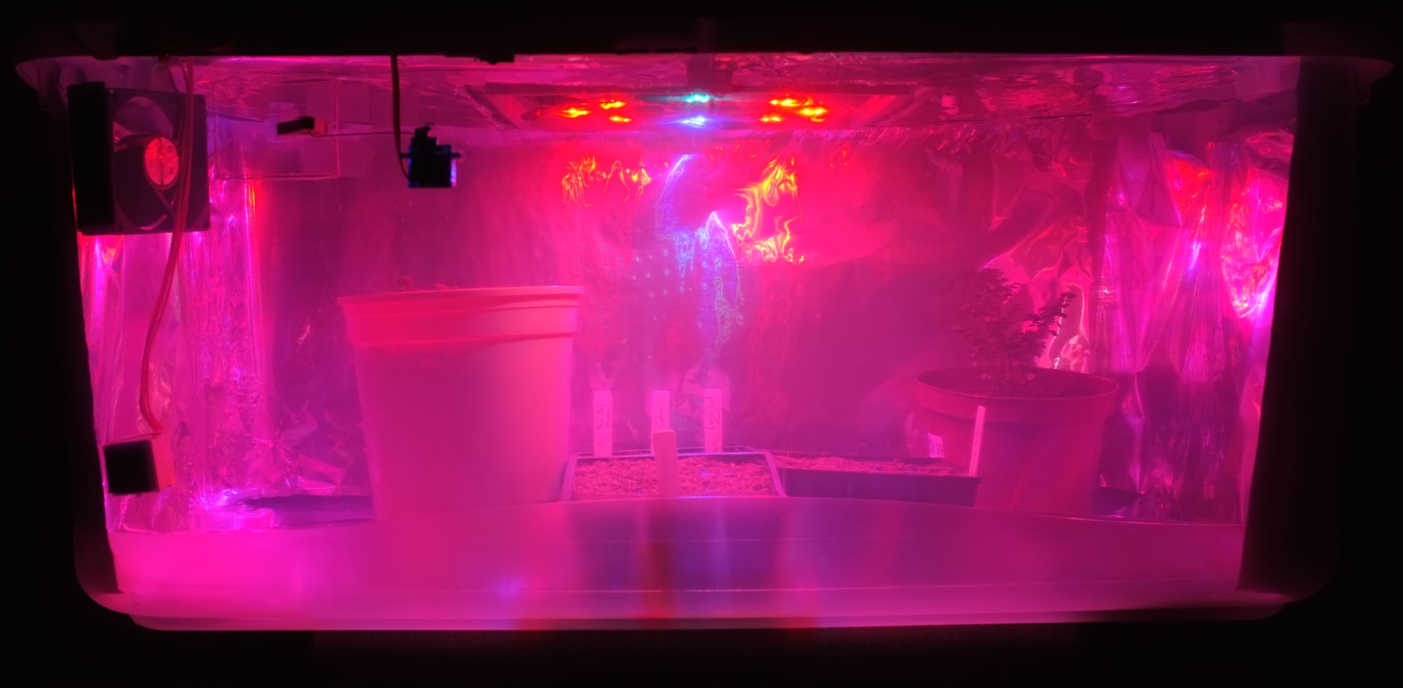
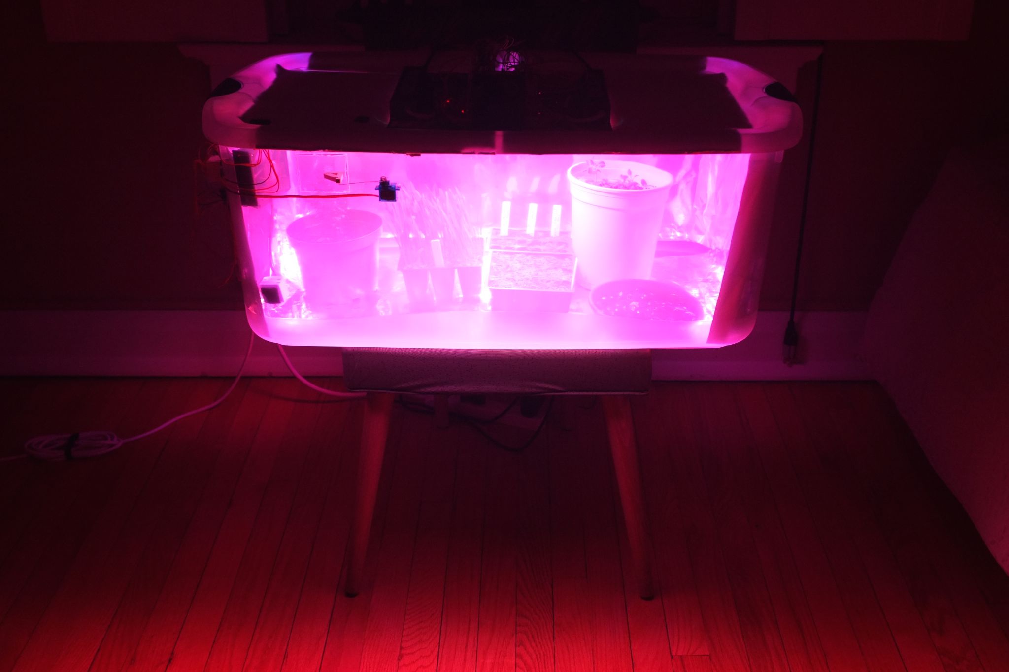
To help focus on the electronics at this stage, I decided to go with a pre-made option for the greenhouse container. I knew I wanted something that could be totally enclosed, to control temperature and humidity. I decided to start with something cheap, so I found a 106 quart Rubbermaid tub at the local hardware store.
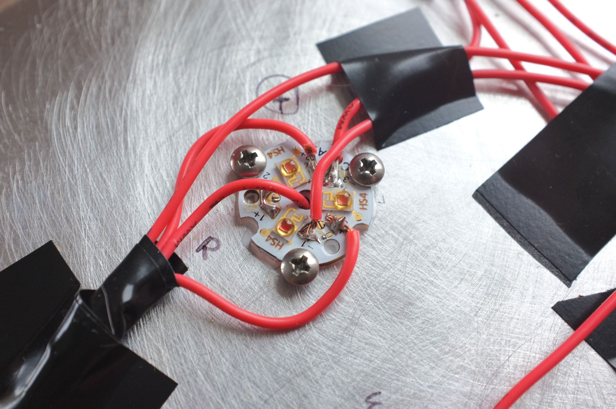
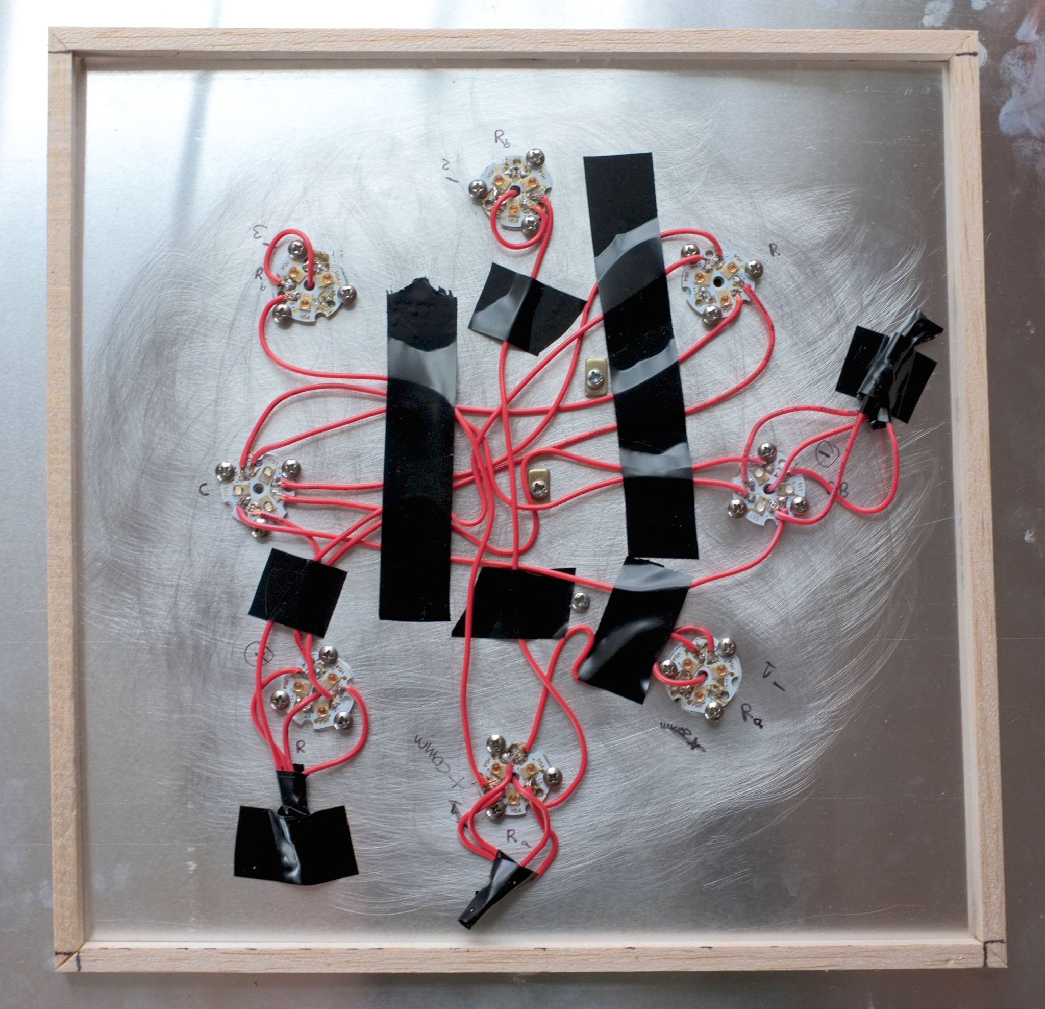
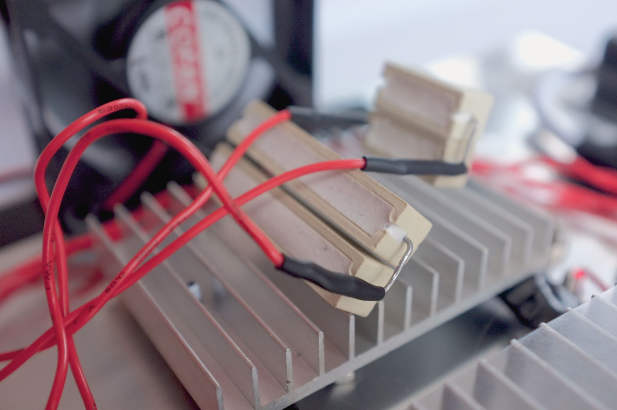
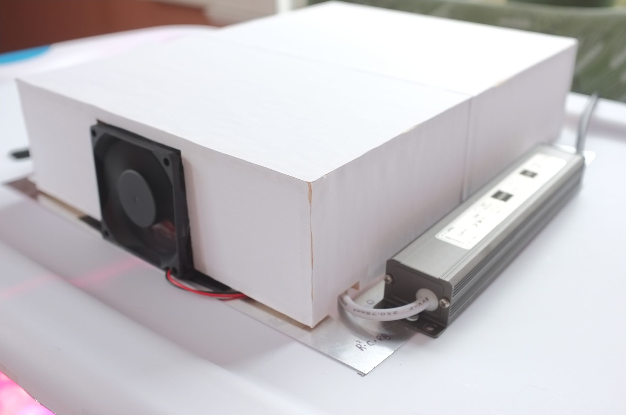
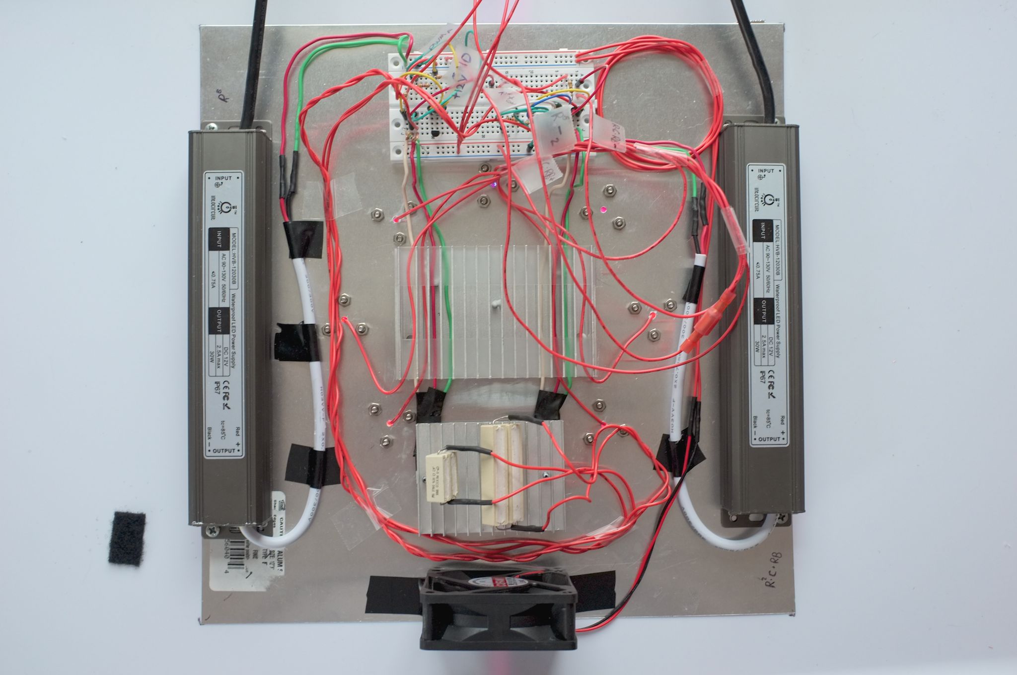
Since heat-sinking the high-power LEDs is a significant concern, I chose a 1-foot square sheet of aluminum for mounting the LEDs. The aluminum is a decent thermal conductor yet soft enough to easily drill holes in for mounting items with screws. The Tri-Star bases have holes for #4 screws, so I bought 3x #4 machine screws and nuts per base. In the middle of my aluminum plate I mounted a re-used heatsink and around it I mounted each of the Tri-Star bases, with heatsink paste on all of them. I drilled extra holes lining up with the hole in the center of the Tri-Star bases to give me ports through which to route back wires. After mounting the LEDs I mapped out a plan for wiring together my 6 different series of LEDs.
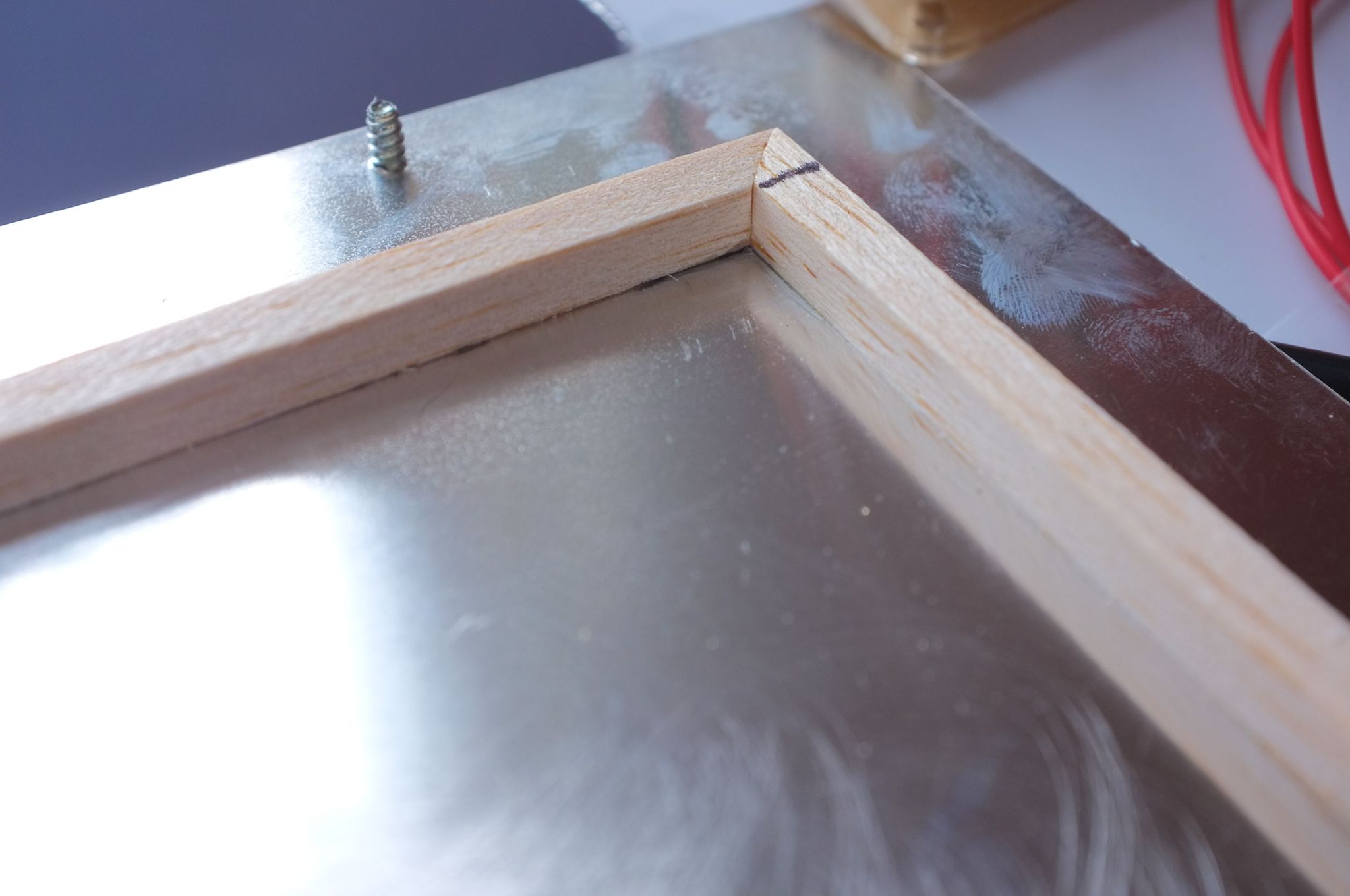
Then I cut a smaller hole in the lid of the container, leaving a 0.5" edge for the aluminum sheet to lay. I also superglued a balsa-wood lip on the underside of the sheet so it couldn't slide out of alignment with the hole in the lid, potentially damaging the LEDs or wiring.
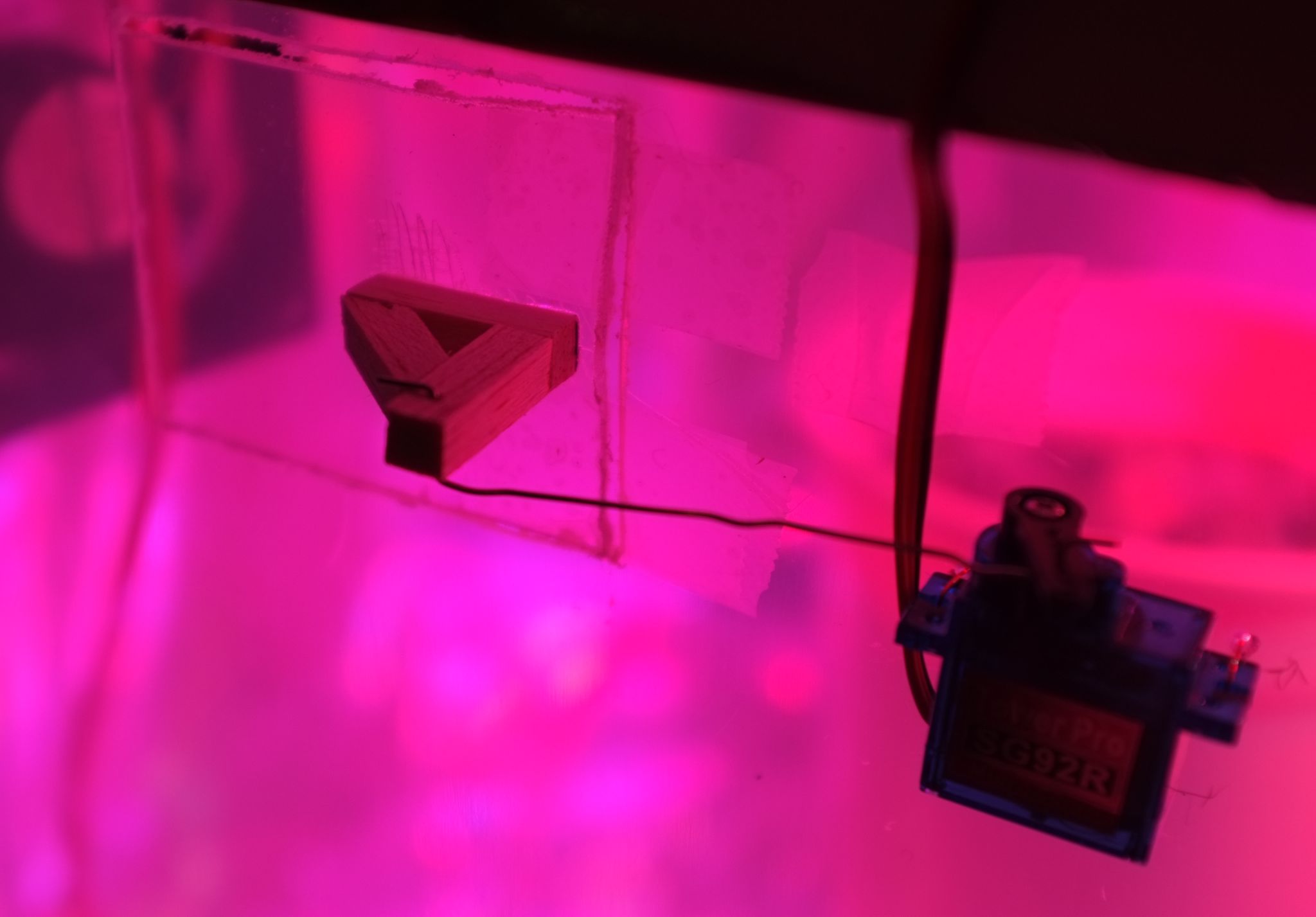
Finally, I cut a square section out of the side of the container, fairly high up, to act as my vent. After filing the edges to keep from getting caught up on burrs, I made a hinge out of tape, making the cut-out section into a door. I fashioned a small lever-arm out of balsa-wood and connected it to a servo with a bent piece of wire.
Humidity and temperature sensors
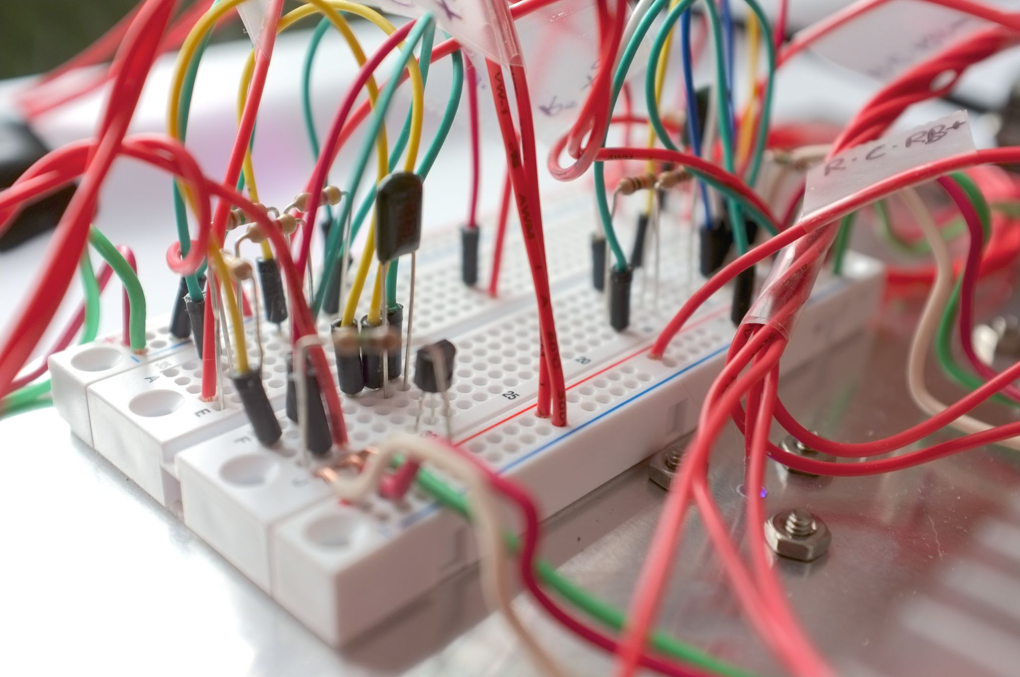
To know how to control the greenhouse we need to know what the current conditions are. I had experience with simpler temperature sensors like the TMP36, but ultimately ended up choosing the Honeywell HIH6100 series. This sensor appealed to me because it reported relative humidity (RH) and temperature and communicated digitally with just 2 pins using an Arduino-supported protocol called I2C. This code worked great for quickly getting readings from the sensors.
I made the mistake, however, of assuming that being able to chain I2C devices together would mean I could connect multiple HIH6100's. However, I couldn't find a way to change the slave address for my 2nd HIH6100 so that meant I had to come up with a way to multiplex them. Initially I tried using 2N3904 transistors to turn on the power to one sensor at a time, but that just had the effect of interrupting communication for the other sensor on the I2C bus. Instead, the solution that worked was to use the 2N3904's to connect only one sensor's SDA (data) pin to the Arduino at a time. Then the process for measuring from two sensors becomes:
- Write HIGH to digital out for 2N3904 connected to Sensor A
- Request measurement from Sensor A
- Write LOW to digital out for 2N3904 connected to Sensor A
- Write HIGH to digital out for 2N3904 connected to Sensor B
- Request measurement from Sensor B
- Write LOW to digital out for 2N3904 connected to Sensor B
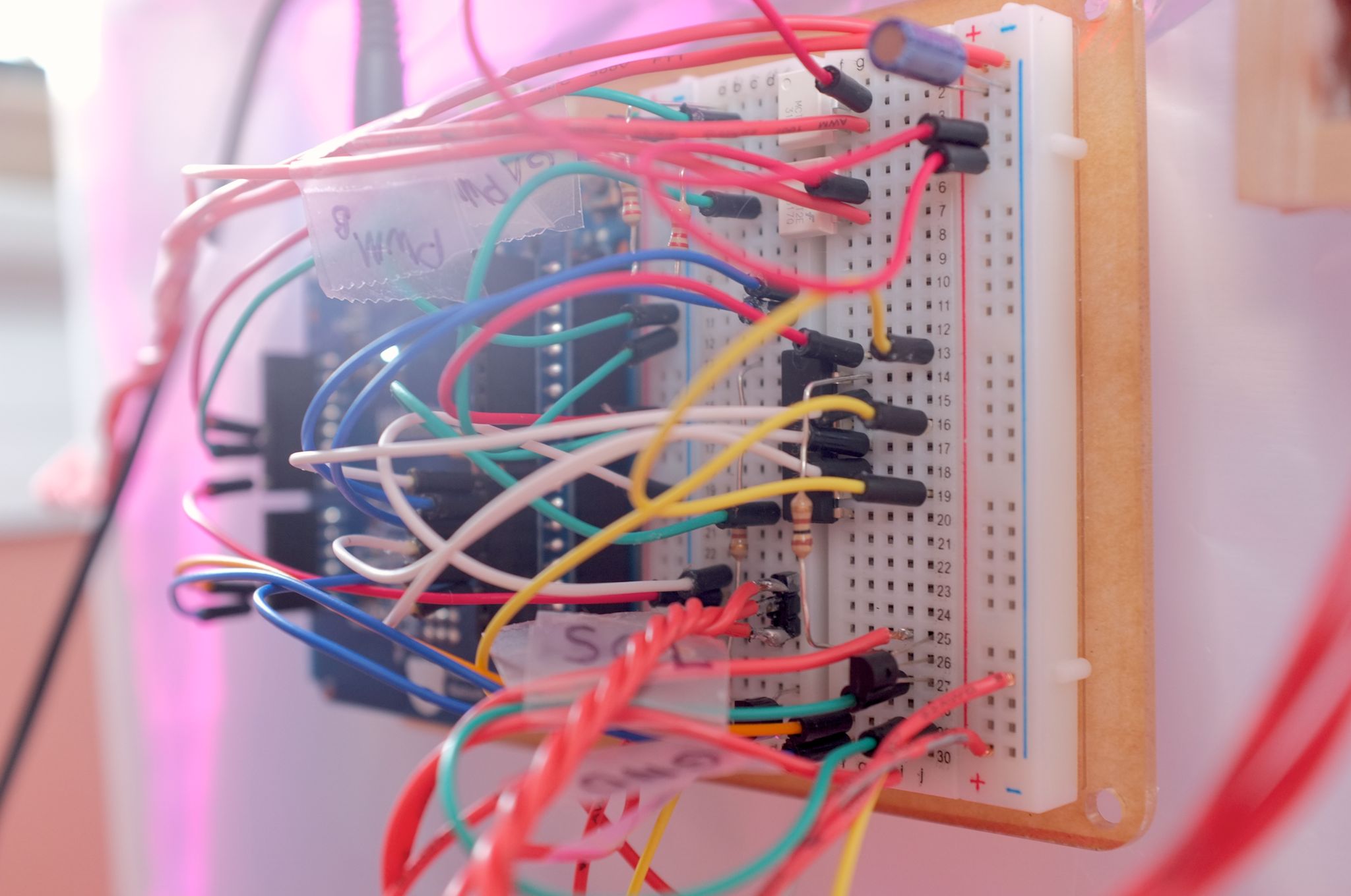
Bluetooth LE shield for Arduino
A while back I purchased the RedBearLab Bluetooth LE shield for Arduino to play around with the Bluetooth LE support in iOS. If you're like me, you're new to Bluetooth LE development so the vast amount of new terminology is overwhelming at first. In RBL's official SDK you'll primarily find demos for UART and Firmata. The UART project simply sets up a bi-directional serial communication tunnel between the Arduino and iOS. Unfortunately this is a rather contrived example of Bluetooth LE communication, which is primarily designed to work through a system called GATT.
In practical terms this means you create a fixed description of various properties that can be read or written to. The proprieties are named Characteristics and the characteristics are organized together into Services. It is common for a single characteristic to represent a single basic datatype such as an int, float, or boolean. A characteristic can have several modes:
- Read – Can be read
- Write – Can be written to, won't send an ACK
- Write With Response – Can be written to, will send ACK/NACK
- Notify – Slave transmits when the value changed
Read and Write are fairly self explanatory. Notify is great for informing the BLE client when a value has changed instead of requiring the client to poll the slave every so often.
The Arduino SDK for interfacing with the Nordic n8001 in the RedBearLabs shield relies on an abstraction called ACI. The default way of interfacing with the shield is by polling for updates over the ACI communication channel. I believe it's theoretically possible to use interrupts to replace the polling, but I haven't gone that far. Instead, you simply call aci_loop(), usually once per cycle of your Arduino sketch's loop(). This dispatches any queued messages to the shield and polls for any messages from the shield for you. Inside the aci_loop() function you switch() on the ACI Event's code to determine if that message indicates a change in status, receipt of data, an error, etc.
To change the GATT profile, with the Services and Characteristics, you need to download a Windows-only app from Nordic Semiconductor called nRFgo Studio. I believe I had to register an account, but ultimately you shouldn't have to pay anything. I successfully ran the app in VirtualBox on my Mac. Once you have the app installed, you'll want to download the Arduino SDK from Nordic and look for the "examples" folder. It's the .xml that you'll actually open from within the nRFgo Studio app. From there, the only two tabs I've changed anything on are "GATT Services" and "GAP Settings". Without going into all the details, I can say that to create your own custom Services and Characteristics you must choose the options to create new templates and then drag the templates into the center list. You'll also want to "nRF8001 Setup > Edit 128 bit UUIDs..." and add a new "base" UUID. One simple way is typing "uuidgen" at the command line in OSX. Once you've finished your configuration, choose "nRF8001 Setup > Generate Source Files > Generate only services.h" and choose where to save. You'll copy the new services.h into your Arduino project folder.
The way you implement the Bluetooth LE Services and Characteristics was a little counter-intuitive to me. The Nordic nRFgo Studio application creates a services.h file with your configuration. In it, it #defines a number of named "pipes", each one which is uni-directional. A single Characteristic has individual pipes for each mode: read, write, write with response, notify, etc. You use these pipe identifiers to determine for which Characteristic data was received, or through which Characteristic to transmit data to the client. When a client WRITEs to the BLE shield or the BLE shield NOTIFYs the client, the data sent/received is ephemeral and the shield acts just as an intermediary. However, Characteristics that can be READ maintain that value in the memory of the BLE shield and requests by the client for that value are delivered directly from the shield without involving the application controller (e.g. the Arduino). The pipe names for the READs are postfixed counter-intuitively with "SET", I suppose signifying that you're setting the value in the board's memory.
Balancing two goals with one passive control
Although more serious greenhouses often have active control over CO2 level, temperature, and humidity it's not uncommon for a greenhouse to have little control other than the opening and closing of louvers to let in outside air. In this small greenhouse we have one similar control: the vent flap. The LEDs are efficient enough that they don't create enough heat to act as a heater.
When the flap is open our circulation fan is directing inside air out the vent, acting to equalize the interior conditions (humidity and temperature) with the exterior conditions. When the flap is closed, several things contribute to the internal conditions. Standing water can evaporate and plants will transpire, both raising the humidity. Sunlight may enter greenhouse and warm the trapped air. Choosing when to open and when to close the vent flap is key to keeping the interior climate at our goal, e.g. 70°F and 50% relative humidity (RH).
I call the vent flap a passive control because in a best case scenario it has two options: maintain the natural internal climate or equalize with the external climate. An active control would look like a heater or A/C that can force the climate towards a desired set-point. The choice of when to operate our vent flap is complicated by the fact that it must attempt to satisfy two independent goals: a fixed temperature and a fixed humidity.
To illustrate why achieving both goals with one control is complicated, consider the case where external temperature drops dramatically at night. The greenhouse's internal temperature is very near it's goal of 70°F, but transpiration from the plants is raising the humidity too high. If you open the vent to try and reduce RH by 1% you risk dropping the temperature by 20°! Obviously you need to weigh both the plusses and minuses.
In another situation, the greenhouse could be just 1° above its temperature set-point yet have excellent interior humidity. If there is a very slight temperature difference between interior and exterior, it would take a long time for the venting to reduce our internal temperature. However, if there is a large difference in humidity that long venting process could drastically reduce the interior humidity. In this case, trying to achieve the small temperature adjustment wasn't worth the damage done to our humidity level.
One solution is to take into account both the need for adjustment as well as the opportunity for adjustment of each goal. The 'need' for adjustment can be represented as Need = Xgoal – Xinterior. The 'opportunity' for adjustment can be expressed as Opportunity = Xinterior – Xexterior. We can then express the "necessity" of opening the vent as Necessity = Need * Opportunity. Only when you have both the "need" and "opportunity" will the "necessity" be a positive value. No amount of need combined with zero opportunity will result in a positive necessity, which turns out to accurately describe real life.
Now to take into account the necessity for both temperature and humidity we add the two together, Ntotal = Ntemp + Nhum. For completeness, we add coefficients to each term that we can tweak to balance both the difference in units but also what we perceive as their relative importance: Ntotal = A*Ntemp + B*Nhum. The end result is Ntotal, which has the characteristic of being positive when venting will help us reach one or both goals or less than zero when venting won't help either goal or will help one goal but significantly hurt the other.